Tool Clamping Technology
A look at the development of tool clamping systems essentially shows two core aspects: On the one hand, the variety of products has increased considerably over the years, and on the other hand, precision clamping systems are becoming increasingly important. These developments can be justified by the fact that with increasing quality and performance of machine tools, the demands on process reliability as well as on tool life are also increasing. Quick-change systems and modular construction kits offer a wide range of possibilities to enable quick changeover of the clamping devices and to make production more flexible. Due to the increasing digitization in production in recent years, sensors in clamping systems are becoming more and more important. Sensors that are integrated directly into the clamping system provide important data during machining and ensure condition monitoring of the tool and the associated holder. Particularly in mass production, machinists are gradually turning to intelligent manufacturing structures with a high degree of automation.
The different interfaces to the machine
In practice, machine and spindle are often connected via a taper shank. In this case, standardized interfaces are essential for accommodating the toolholders in the machine. These differ in their automation capability, clamping reliability, changeover accuracy and the optimum speed ranges. The toolholders must optimally transfer the required machining force from the spindle to the tool. Rigidity, clamping force, vibration damping and concentricity cannot be neglected here.
The following interfaces exist in tool clamping technology:
- Morse taper (MK): The Morse taper is one of the oldest tool interfaces and is standardized according to DIN 228. Mostly, this interface is used in hand-operated drilling machines, where the torque transmission takes place by means of static friction in the taper. The MK interface is self-locking and therefore cannot be automated, as it must be manually removed from the locating taper. Steep tapers and hollow shank tapers are mainly used in lathes and machining centers today.
- Steep taper (SK): The SK-
 interface is standardized according to DIN 69871 and 2080. The much steeper and widely used steep taper is not self-locking due to its relatively large taper angle. It centers well during tool changes and is easy to release. With this interface, the tool must be pulled continuously into the holder. The force transmission is frictionally engaged via the taper. Reliable torque transmission is ensured via grooves in which sliding blocks on the work spindle engage, thus enabling a positive fit. At high speeds, the forces that occur increase and bring the SK interface to its limits, as centrifugal or centrifugal forces expand the taper sleeve of the main spindle. As a result, the tool is pulled further in during operation and jams at standstill. For this reason, it was necessary to develop an interface suitable for very high speeds, which gave rise to the hollow shank taper.
- Hollow shank taper (HSK): The HSK-interface is standardized according to DIN 69893 and can be regarded as a further development of the steep taper. The hollow shank taper was developed in a research project at RWTH Aachen University in close cooperation with partners from industry. Compared to the SK interface, the hollow shank taper is around 50% lighter and 30% smaller, which should not only simplify but also accelerate tool changes. The smaller taper angle ensures that the HSK interface is in contact with the face of the work spindle. This results in high rigidity and changeover accuracy in the axial direction. The torque is transmitted non-positively via taper and contact surfaces and positively via two drive slots. The hollow shank taper is particularly suitable for high rotational frequencies, as the high forces push the clamping elements outwards and increase the clamping force on the taper surface.
Holders for various tools
Tools can be clamped differently on the steep or hollow shank taper with the help of different holders. The tools should be clamped in the respective machining centers in such a way that a very good axial and radial run-out accuracy as well as a high repetition accuracy in the positioning during the tool change are guaranteed. Attention should also be paid to good bending or torsional rigidity and the possibility of high rotational frequencies. The different holders include:
- Collet Chucks
- Weldon Tool Holder
- Drill Chucks
- Skrink Chucks
- Hydraulic Chucks
Workpiece Clamping Technology
Fast and precise clamping of workpieces is crucial for the efficiency and performance of machining. For production to be profitable in the long term, the manufacturing process must be efficient and economical. Workpiece clamping technology can make an important contribution here by ensuring a secure connection between the machine table and the workpiece.
The different clamping devices
Which holder is the most suitable for process-safe clamping of the workpiece on the machine essentially depends on the respective machining process and the shape of the component to be machined. The different clamping devices are shown below:
- Chucks: Power or hand-operated chucks are used in particular on lathes. It consists of a flange that connects the machine spindle to the chuck body. This encloses and stabilizes the clamping point. A so-called draw tube adapter connects the chuck coupling with the clamping cylinder of the machine and opens or closes the clamping system.
The coupling holds and moves the clamping head, which fixes the workpiece. A basic stop is used for exact positioning of the workpiece, this can be removed to obtain full clearance for bar machining. The chucks usually have three jaws, but four, six or more jaws can be used for other geometries or thin-walled components. The clamping jaws have a great influence on the clamping quality and the clamping reliability. A distinction is made between hard and soft clamping jaw sets. Hard jaws are wear-resistant, suitable for large clamping forces and have toothed clamping surfaces, which, however, damage the surface of the workpiece. Soft jaws do not damage the surface of the workpiece, have a high repeat clamping accuracy and can be adjusted in diameter as well as depth. To ensure use at higher machining speeds, the chuck is equipped with centrifugal force compensation. This allows clamping force losses to be compensated. When loading the chuck, the workpiece is guided into the chuck head and positioned by the basic stop. The chuck head is pulled into the taper and closes around the workpiece, pulling it forcefully against the base stop. The resulting rigid clamping reduces vibrations during machining and stabilizes the workpiece.

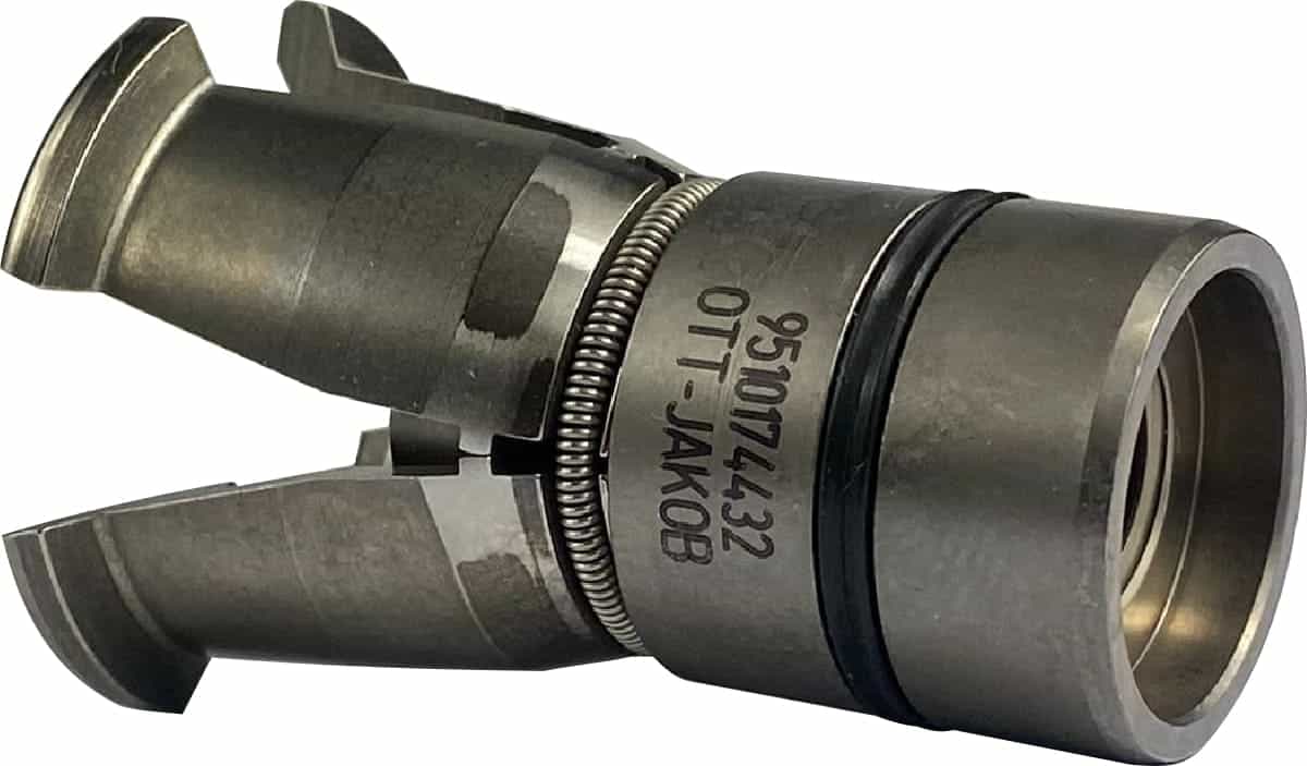
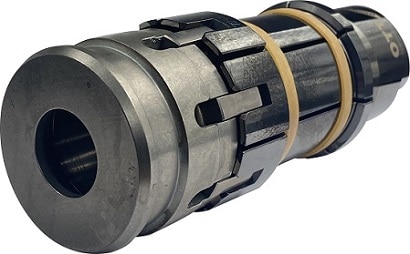
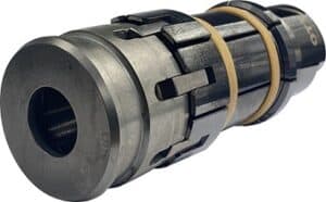
- Mandrels: Typically, the mandrel is mounted directly on a machine spindle and centered via a tapered or cylindrical mounting. Thus, during lathe turning, the rotary movements and torques are transmitted to the clamped workpiece. The internal clamping takes place in a bore or internal contour. The holding element of the clamping mandrel is the segment clamping sleeve. The clamping sleeve is moved by a coupling, which in turn is held by a mandrel body, and is actuated by the clamping device on which the mandrel is mounted. The coupling shell connects the clamping sleeve and the coupling. With the mandrel, the base stop also positions and stabilizes the workpiece and, on top of that, protects against contamination in the clamping system. When the workpiece is loaded, the clamping sleeve is pulled onto the taper and expands, making contact with the workpiece over its entire diameter and pulling it against the base stop. This stabilizes the workpiece and reduces vibrations.
- Collets: In contrast to the mandrel, the collet is used for external clamping. It enables accurate, fast and force-fit clamping. The collet consists of a tapered radially slotted sleeve with a round, and sometimes square or hexagonal bore. This is accompanied by a collet holder with a matching inner taper. Clamping is effected by means of a union nut, with which the collet is pressed into the inner taper of the receptacle. The slot uniformly compresses the bore in the chuck, holding the workpiece in a force-fit.
Tool Clamping Technology
A look at the development of tool clamping systems essentially shows two core aspects: On the one hand, the variety of products has increased considerably over the years, and on the other hand, precision clamping systems are becoming increasingly important. These developments can be justified by the fact that with increasing quality and performance of machine tools, the demands on process reliability as well as on tool life are also increasing. Quick-change systems and modular construction kits offer a wide range of possibilities to enable quick changeover of the clamping devices and to make production more flexible. Due to the increasing digitization in production in recent years, sensors in clamping systems are becoming more and more important. Sensors that are integrated directly into the clamping system provide important data during machining and ensure condition monitoring of the tool and the associated holder. Particularly in mass production, machinists are gradually turning to intelligent manufacturing structures with a high degree of automation.
The different interfaces to the machine
In practice, machine and spindle are often connected via a taper shank. In this case, standardized interfaces are essential for accommodating the toolholders in the machine. These differ in their automation capability, clamping reliability, changeover accuracy and the optimum speed ranges. The toolholders must optimally transfer the required machining force from the spindle to the tool. Rigidity, clamping force, vibration damping and concentricity cannot be neglected here.
The following interfaces exist in tool clamping technology:
- Morse taper (MK): The Morse taper is one of the oldest tool interfaces and is standardized according to DIN 228. Mostly, this interface is used in hand-operated drilling machines, where the torque transmission takes place by means of static friction in the taper. The MK interface is self-locking and therefore cannot be automated, as it must be manually removed from the locating taper. Steep tapers and hollow shank tapers are mainly used in lathes and machining centers today.
- Steep taper (SK): The SK-interface is standardized according to DIN 69871 and 2080. The much steeper and widely used steep taper is not self-locking due to its relatively large taper angle. It centers well during tool changes and is easy to release. With this interface, the tool must be pulled continuously into the holder. The force transmission is frictionally engaged via the taper. Reliable torque transmission is ensured via grooves in which sliding blocks on the work spindle engage, thus enabling a positive fit. At high speeds, the forces that occur increase and bring the SK interface to its limits, as centrifugal or centrifugal forces expand the taper sleeve of the main spindle. As a result, the tool is pulled further in during operation and jams at standstill. For this reason, it was necessary to develop an interface suitable for very high speeds, which gave rise to the hollow shank taper.
- Hollow shank taper (HSK): The HSK-interface is standardized according to DIN 69893 and can be regarded as a further development of the steep taper. The hollow shank taper was developed in a research project at RWTH Aachen University in close cooperation with partners from industry. Compared to the SK interface, the hollow shank taper is around 50% lighter and 30% smaller, which should not only simplify but also accelerate tool changes. The smaller taper angle ensures that the HSK interface is in contact with the face of the work spindle. This results in high rigidity and changeover accuracy in the axial direction. The torque is transmitted non-positively via taper and contact surfaces and positively via two drive slots. The hollow shank taper is particularly suitable for high rotational frequencies, as the high forces push the clamping elements outwards and increase the clamping force on the taper surface.
Holders for various tools
Tools can be clamped differently on the steep or hollow shank taper with the help of different holders. The tools should be clamped in the respective machining centers in such a way that a very good axial and radial run-out accuracy as well as a high repetition accuracy in the positioning during the tool change are guaranteed. Attention should also be paid to good bending or torsional rigidity and the possibility of high rotational frequencies. The different holders include:
- Collet Chucks
- Weldon Tool Holder
- Drill Chucks
- Skrink Chucks
- Hydraulic Chucks
Workpiece Clamping Technology
Fast and precise clamping of workpieces is crucial for the efficiency and performance of machining. For production to be profitable in the long term, the manufacturing process must be efficient and economical. Workpiece clamping technology can make an important contribution here by ensuring a secure connection between the machine table and the workpiece.
The different clamping devices
Welcher Halter für ein prozesssicheres Spannen des Werkstücks auf der Maschine am geeignetsten ist, hängt im Wesentlichen vom jeweiligen Bearbeitungsverfahren und der Form des zu bearbeitenden Bauteils ab. Im Folgenden werden die unterschiedlichen Spannmittel aufgezeigt:
- Chucks: Power or hand-operated chucks are used in particular on lathes. It consists of a flange that connects the machine spindle to the chuck body. This encloses and stabilizes the clamping point. A so-called draw tube adapter connects the chuck coupling with the clamping cylinder of the machine and opens or closes the clamping system. The coupling holds and moves the clamping head, which fixes the workpiece. A basic stop is used for exact positioning of the workpiece, this can be removed to obtain full clearance for bar machining.
The chucks usually have three jaws, but four, six or more jaws can be used for other geometries or thin-walled components. The clamping jaws have a great influence on the clamping quality and the clamping reliability. A distinction is made between hard and soft clamping jaw sets. Hard jaws are wear-resistant, suitable for large clamping forces and have toothed clamping surfaces, which, however, damage the surface of the workpiece. Soft jaws do not damage the surface of the workpiece, have a high repeat clamping accuracy and can be adjusted in diameter as well as depth. To ensure use at higher machining speeds, the chuck is equipped with centrifugal force compensation. This allows clamping force losses to be compensated. When loading the chuck, the workpiece is guided into the chuck head and positioned by the basic stop. The chuck head is pulled into the taper and closes around the workpiece, pulling it forcefully against the base stop. The resulting rigid clamping reduces vibrations during machining and stabilizes the workpiece.
- Mandrels: Typically, the mandrel is mounted directly on a machine spindle and centered via a tapered or cylindrical mounting. Thus, during lathe turning, the rotary movements and torques are transmitted to the clamped workpiece. The internal clamping takes place in a bore or internal contour. The holding element of the clamping mandrel is the segment clamping sleeve. The clamping sleeve is moved by a coupling, which in turn is held by a mandrel body, and is actuated by the clamping device on which the mandrel is mounted. The coupling shell connects the clamping sleeve and the coupling. With the mandrel, the base stop also positions and stabilizes the workpiece and, on top of that, protects against contamination in the clamping system. When the workpiece is loaded, the clamping sleeve is pulled onto the taper and expands, making contact with the workpiece over its entire diameter and pulling it against the base stop. This stabilizes the workpiece and reduces vibrations.
- Collets: In contrast to the mandrel, the collet is used for external clamping. It enables accurate, fast and force-fit clamping. The collet consists of a tapered radially slotted sleeve with a round, and sometimes square or hexagonal bore. This is accompanied by a collet holder with a matching inner taper. Clamping is effected by means of a union nut, with which the collet is pressed into the inner taper of the receptacle. The slot uniformly compresses the bore in the chuck, holding the workpiece in a force-fit.
Automatic Tool Clamping
Pull-in force measuring device


Work Supports

Hydraulic Cylinders
